Step 1: Internal Printer Connections
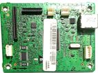
If you are reinstalling this board inside the printer housing, connect the dedicated ribbon cables and wire harnesses into their keyed sockets:
Flat Flexible Cables (FFC / Ribbon Cables): Carefully slide the flat silver-tipped ribbon cables (from the scanner unit and print engine) directly into the corresponding wide horizontal slot connectors on the board. Secure the locking tabs down tightly.
Wire Harness Connectors: Plugin the white plastic wire assemblies (from the control panel, power supply, and internal sensors) into the matching white keyed header pins distributed across the board. They only fit in one orientation.
Step 2: External Computer Connection
Once mounted and closed inside the printer body:
USB Port Connection: Use a standard USB Type-B cable (the squarish printer connector) to plug into the metal USB receptacle on the right side of the board.
Computer Connection: Connect the opposite end (USB Type-A or Type-C) directly to your computer to allow data transmission.
If you are replacing a faulty logic card, make sure to double-check that your exact ribbon cable positions and part numbers align properly before screwing the board down.